SM7LCB - 1.3 GHz station
Last updated 14 December 2010.Hi, and welcome to my page regarding my 1.3 GHz (23 cm) transverter. The content is:
- History of 1.3 GHz
- Block diagram
- Photo of the transverter
History of 1.3 GHz
This transverter have since 2004 been used by me on 23 cm and with remote control.
Block diagram
Below is the principal diagram of the 1.3 GHz transverter.
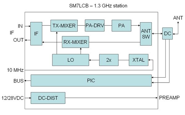
The following functions have each block in the transverter:
- IF is the IF switch for 144 MHz IF used in my transverter system.
I use this because all my transverters is cascade connected so I only have one IF cable up to the antennas.
This IF switch also have the RX/TX switching between the RX and TX path of the transverter. - TX-MIXER is a design by Lars/SM0IQC and Viljo/ES5PC.
- PA-DRV this is an Ericsson drive power amplifier with about 0 dBm in it give 7 W out at 12 VDC.
- PA this is one Ericsson TUG module giving about 50 W out at 28 VDC.
- ANT-SW is a surplus heavy duty coax relay.
- DC is a directional coupler (from Ericsson) for measure forward and reflected power with the PIC.
- RX-MIXER is a design by Lars/SM0IQC and Viljo/ES5PC.
- LO is 1152 MHz multiplier/drive a design by Lars/SM0IQC and Viljo/ES5PC.
- 2x is a small (home made) multiplier of the 96 MHz signal from the XTAL.
- XTAL is small 96 MHz oscillator (from Ericsson base station) with 10 MHz locking.
- PIC is home made controller of the transverter.
It use ICOM bus connection to the controller of the receiver system.
It control the IF-switch and supervision of output power, temperature etc.
TX-control is via DC level on the IF coax (+DC at TX). - DC-DIST block is handling DC-switching controlled by the PIC for PA/PREAMP.
Photo of the transverter
The transverter is build in an old NMT (old mobile phone system) base station box with nice small xx for each part of the transverter.
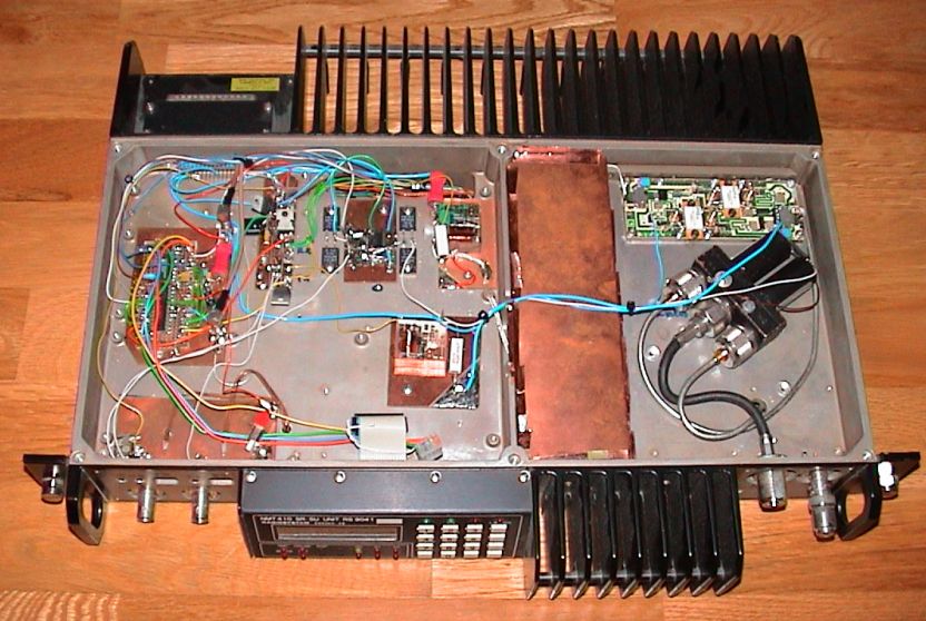 | Picture show the top part of my 1.3 GHz transverter: Left side has the PIC microcontroller together with the DC-DIST and switch. Right side has the PA-DRV under the copper and on top the small final PA (TUG module). There is also the ANT-SW relay. |
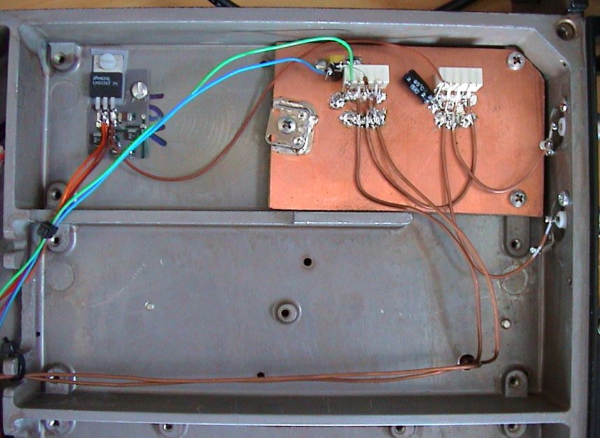
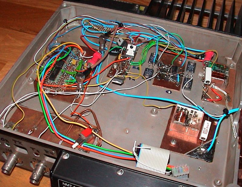 | Close photo of the PIC microcontroller to the left DC-DIST top and rigth side On low left side is ajustment for RX/TX power on the IF side. The two relay was used to switch the PA-DRV and bias to the PA. The later realy have been changed to a P-MOSFET. |
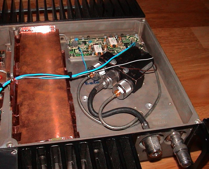 | Close photo of the PA-DRV (left under copper) PA (top) ANT-SW (black relay) |
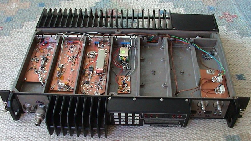 | Picture show the bottom part of my 1.3 GHz transverter from left: - RX-MIXER - LO - TX-MIXER - XTAL and 2x - IF-SW |
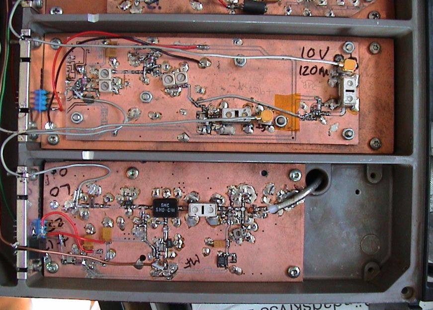 | Close photo of the LO multiplier/driver (upper) RX-MIXER (lower) |
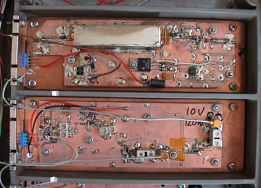 | Close photo of the TX-MIXER (upper) LO multiplier/driver (lower) |
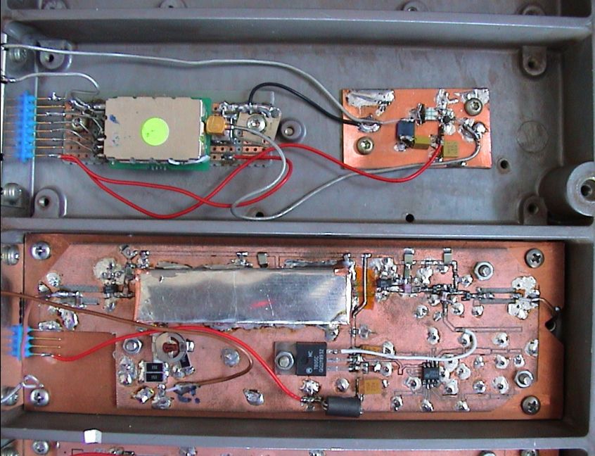 | Close photo of the XTAL and 2x (upper) TX-MIXER (lower) |
 | Close photo of the IF switch and a small DC regulator |
If you want any more information on this page, send an email to me. For address see main page.
| SM7LCB |
End of this page
|
 |