SM7LCB - 2.3 GHz station
Last updated 11 December 2010.Hi, and welcome to my page regarding my 2.3 GHz (13 cm) transverter. The content is:
- History of 2.3 GHz
- Block diagram
- How I build it
- Parts of the transverter
History of 2.3 GHz
I have been QRV on 2.3 GHz (13 cm) from my Öland QTH (JO86GH) since summer 2008. I built the transverter during April to June that year after I got a transverter from the SK0CT team with the wish that I will be QRV on 13 cm and also active. Before this I have been active from my old QTH in Stockholm during 1998 to 2000. I think I during this time borrow a transverter from Per/SM0DFP.
Block diagram
Below is the principal diagram of the 2.3 GHz transverter.
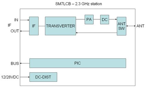
The following functions have each block in the transverter:
- IF is the IF switch for 144 MHz IF used in my transverter system.
I use this because all my transverters is cascade connected so I only have one IF cable up to the antennas. - TRANSVERTER is a DB6NT with build in XTAL (not locked).
- PA this is an Ericsson drive power amplifier modified for the to handle the power from the transverter.
With about 1 W in it give 40 W at 28 VDC. - DC is a directional coupler for measure forward and reflected power to the antenna on the TX path.
- ANT SW is a nice coax relay with SMA connectors.
- PIC is home made controller of the transverter.
It use ICOM bus connection to the controller of the receiver system.
It control the IF-switch and supervision of output power, temperature etc.
TX-control is via DC level on the IF coax (+DC at TX). - DC-DIST block is handling DC-switching controlled by the PIC for PA etc.
How it was built
The transverter is not build in a normal box. This because it shall be inside and also because the build shall go quick. Therefore I build the complete transverter and aluminum plate and then mounted all parts on a chipboard. Maybe not a nice built style but it was quick and easy. the picture below show the nice built and it's working very nice, believe me!
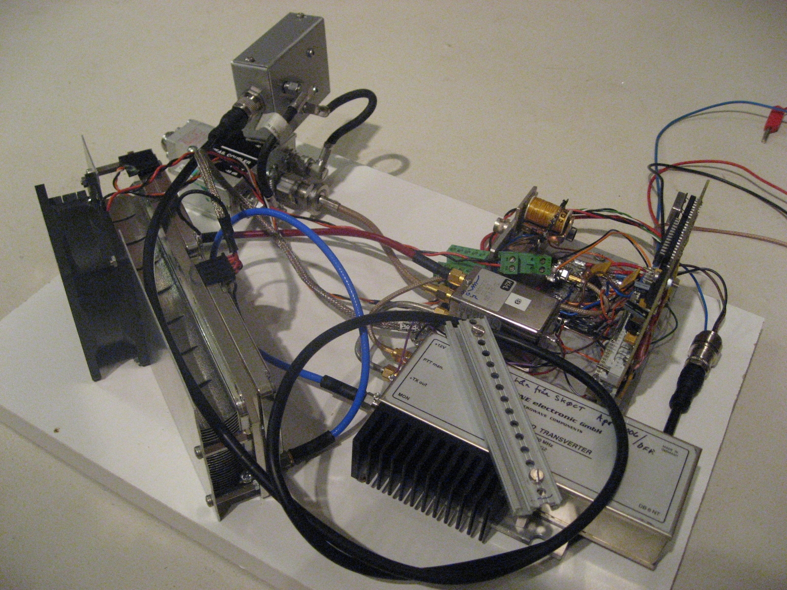 | Picture show all components for my 2.3 GHz transverter: - On top left there is the DC for output supervision. - Below the DC is the PA with the needed fan. - To the right of the PA you see the TRANSVERTER. - Above the TRANSVERTER you see the ANT SW. - Above the ANT SW is the IF SW. - To the right of the ANT/IF SW is the DC board. - And finely to the right of DC is the PIC controller Click to get a better view of the nice design! |
Parts of the transverter
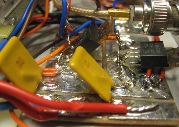 | The DC distribution part consist of some P-MOSFET which is controlled by the PIC microcontroller. - Transverter ON/OFF. - Power amplifier ON/OFF. Missing is, - PREAMP control! Therefore I still don't have any preamp for 13cm! |
 | The
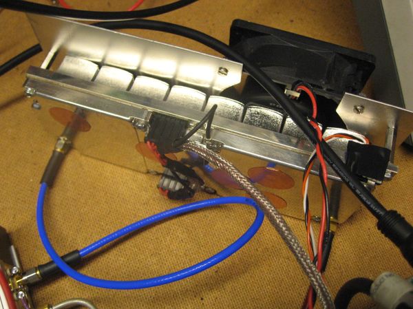
power amplifier (PA) is an Ericsson drive PA for there mobile base
stations. This driver give 40 W with more or less 0 dBm input.
Therefore the the PA is modified to handle the higher output of the
transverter by bypassing the first stages i the PA. The final PA from the mobile station will easy deliver 300 W but I still haven't got time to install it at my site. |
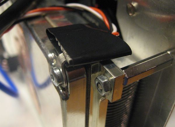 | This is a close look at my temperature measurement part which is handled by the PIC microcontroller. This is one of the way to supervise the PA in the remote operation. |
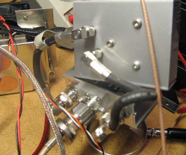 | This
is the directional coupler (DC) together with the logarithmic
amplifiers in the box. This give a nice and easy supervision of the
output power and also the reflected power from the antenna. The directional coupler is Ericsson surplus. |
 | Here is a photo of the unmodified logarithmic amplifiers which is working nice up to 3 GHz. As you see it's Ericsson surplus. |
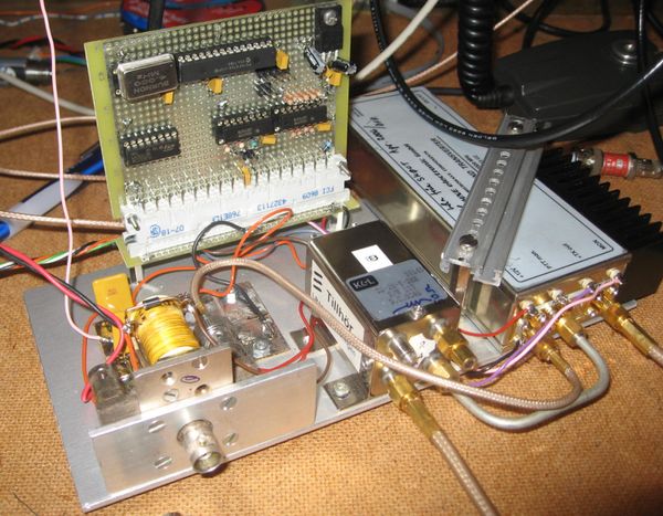 | Here is the 2.3 GHz transverter except PA and directional coupler. The PIC microcontroller is home made and also the software. The IF switch is an old BNC coax relay. The ANT switch is a very nice SMA coax relay (from Ericsson). And the transverter you all see is an DB6NT! |
Do you want any more information on this page, send an email to me. For address see main page.
| SM7LCB |
End of this page
|
 |