SM7LCB - 3.4 GHz station
Last updated 25 July 2010.In the spring of 2008 I bought a 3.4 GHz transverter with a Toshiba PA from Torleif/SM7EYW which he have used at SK7MW. I got it in my hands during the SM5QA meeting 2008. Before the summer of 2008 I rebuild it to function whitin my station by adding IF-switch because I cascade connect all my transverters. For controlling the transverter I added a PIC microcontroller. During 2008 I only worked Håkan/SM7GEP and noted at that time that the frequency stability of the unit was bad. When I mounted up my new 1.9 meter dish during summer 2009 I toke down the transverter for rebuild it with a new local oscillator. The transverter is now QRV with the 1.9 meter dish since 27 of June 2010 and the first QSO was with Christian/OZ2LD.
The transverter is installed on the back of my 1.9 meter dish. The antenna coax to the feed point of the dish is about 1.2 meter, you can read more about the antenna and feeder on this page. Control and IF cables to the transverter are the following:
- IF input from the radio (144 MHz) via RG214/RG58 coaxial cable.
The cascade coupled IF is today connected in the following order 23cm - 13cm - 9cm - 3cm.
- IF output to next transverter (144 MHz) via RG214/RG58 coaxial cable (e.g. 3cm).
- 10 MHz reference frequency for the build in XO.
- BUS connection which in my case today is ICOM-bus using RG58 coaxial cable.
- 12VDC power distribution on the antenna platform.
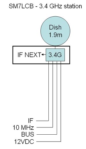 |  |
Inside the transverter box with have the following units and connections,
IF is the IF-switch with normally pass true connection. When transverter is activied via the BUS the PIC will switch the IF into the transverter and the IF output will be disconnected.
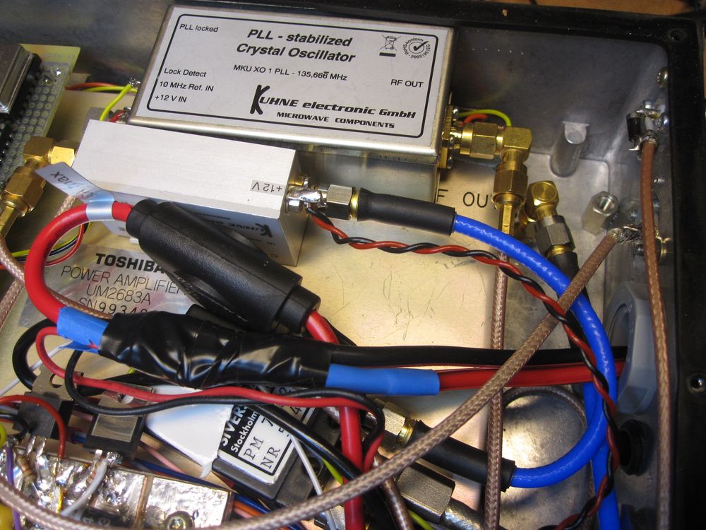
TRANSVERTER is a old DB6NT unit which have been modified for external oscillator input which comes from the XO which also is the new DB6NT stand alone oscillators with 10 MHz reference input.
For transmission there is a PA unit from Toshiba which can give maximum of 40 W and in the receiver line there is a PREAMP from DB6NT (again). The ANT SW is a small SMA coaxial relay which is have a 24 VDC coil.
The complete transverter is controlled by a PIC microprocessor over the BUS. To handle the control of the PIC use DC-switches on the DC unit to switch PA and PREAMP. The PIC will receive the TX signal as a DC-signal on the IF. The PIC then control the complete RX/TX sequence and the connected ANT SW. During both RX and TX the PIC supervise the temperature of the unit and also the output power of the PA during transmission.
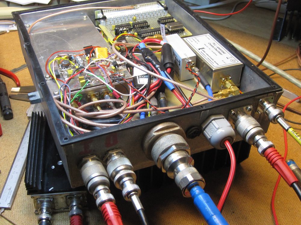
This photo of the unit shows the input connections IF IN, IF OUT, ANT, DC, 10 MHz and BUS.
This photo show the inside of the box. The transverter is hidden to the left under DC switch unit and the PA is hidden to the right under the top PIC unit, and ANT SW with PREAMP and XO.
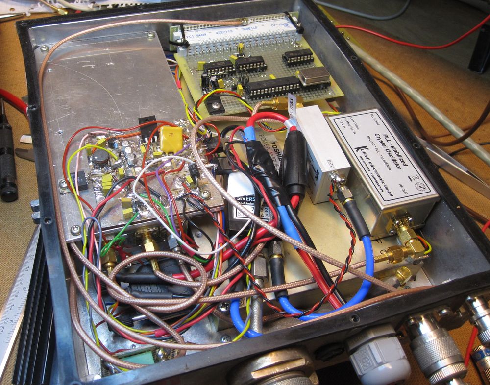
Photo showing the short antenna connection to the antenna relay. The IF switch is shown in the lower lefter corner of the box.
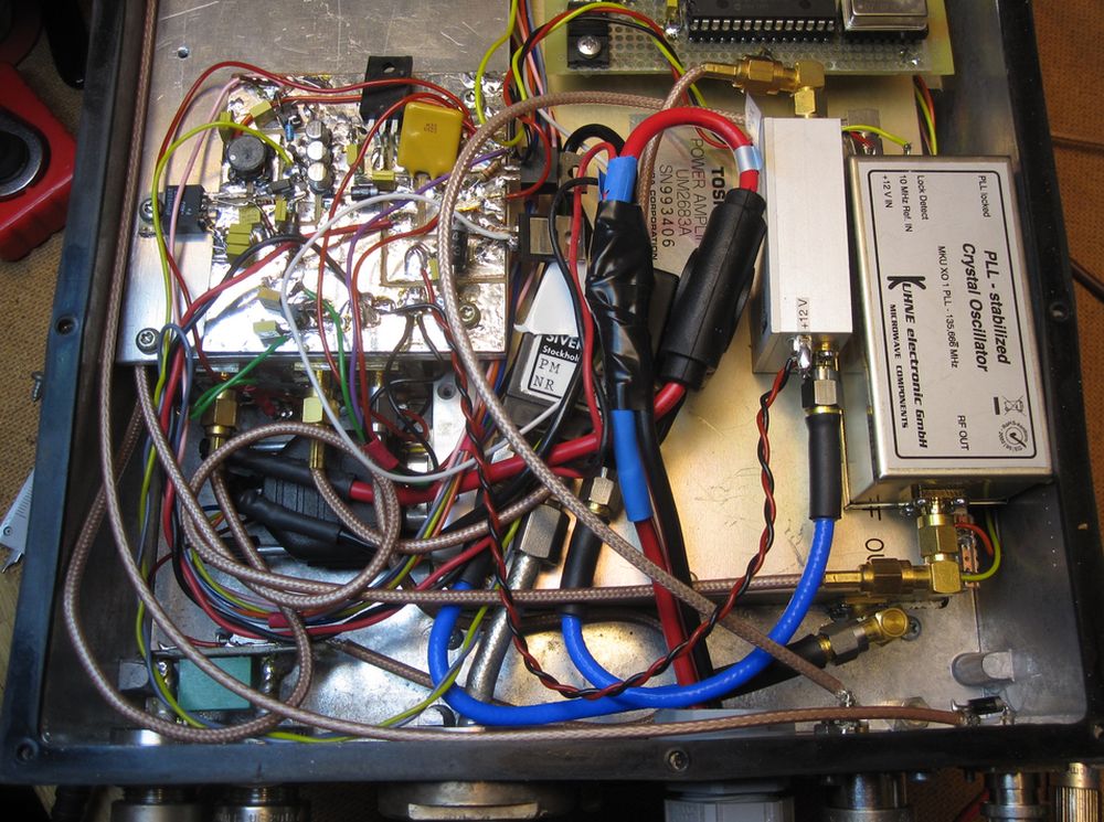
Photo of the preamp and XO unit.
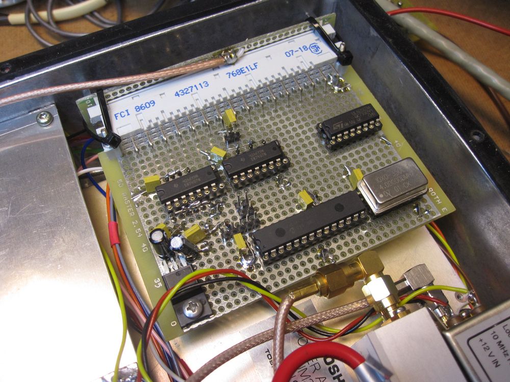
This photo show the PIC microprocessor unit with some interface IC and the larger PIC16F876A CPU.
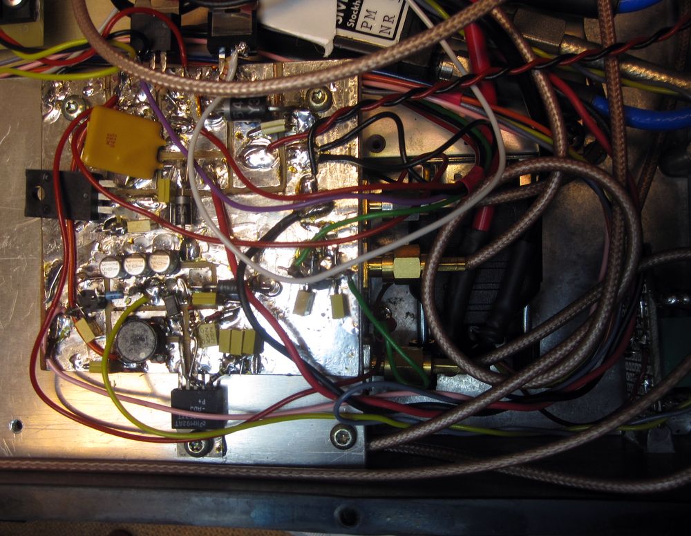
This photo show the DC unit which have the DC input protection, 24VDC DCDC-converter and also two DC-switches for the PA and PREAMP switching.
| SM7LCB |
End of this page
|
 |