SM7LCB - 5 GHz station
Last updated 13 January 2016.Hi, and welcome to my page regarding my 5 GHz (6 cm) transverter. The content is:
- History of 5 GHz
- The new transverter
- Block diagram
- New direction autumn 2011
- Work during 2015
History of 5 GHz
I have been QRV on 5 GHz (6cm) from my Öland QTH (JO86GH) but I don't have any QSO on the band! How?
During summer 2001 I was QRV as SM0LCB/7 in JO86GH with a transverter with both 5 and 10 GHz. The box was the same as my current 10 GHz but with both 5 and 10 GHz. Inside I have only the two DB6NT transverters one for each band e.g. only 200 mW and no preamp. During that summer I on 10 GHz worked:
- OZ/OK5DX/P in JO75JFNo more QSO and no QSO on 5 GHz. On 5 Ghz I only listen to some unknown radar signals. I quit dissatisfied summer on microwave so a rebuild the transverter for only 10 GHz and increased power to 500 mW with a PA from LA6LCA. Later I upgraded to 5 W and also a preamp. Below are some pictures of this transverter:
- SM1FMT in JO97FS
 Test setup at home is SM0 (old QTH) | 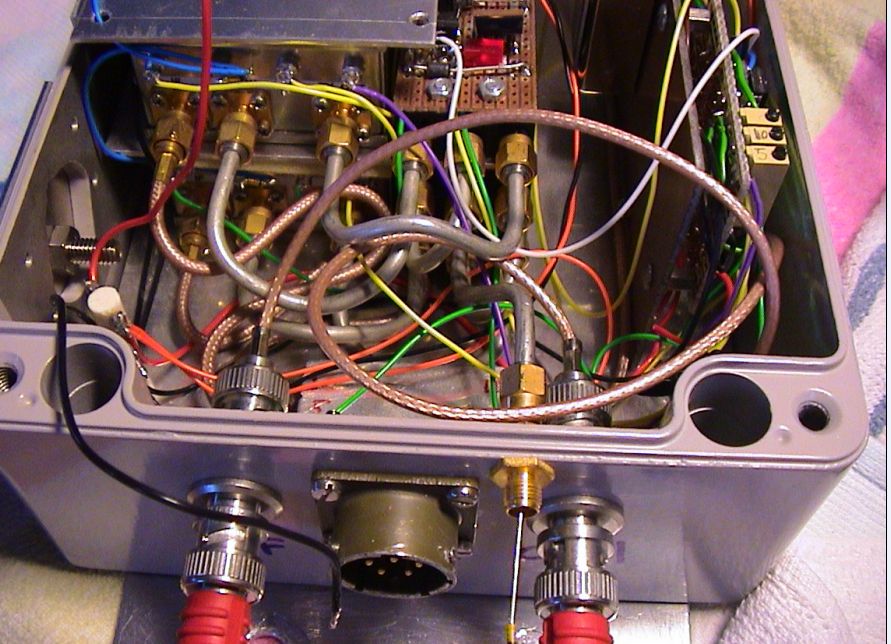 Inside the box with two DB6NT transverter and PIC controller. |  Setup on Öland during summer 2001. Only QRV from antenna site! |
The new transverter
Now the transverter for 5 GHz have been waiting for 10 year it's time to use it again. This time in a own box (same size as 10 GHz) and now with at least 15 W output and preamp. The transverter will also be connected to new LO with 10 MHz locking. As usual many items comes from DB6NT. There will be a PIC controller for the remote operation of the transverter in same way as I control all my transverters and rotors using the ICOM-bus.
My hope is to get it ready to summer 2011 e.g. 10 year after last time I was QRV on 6cm. Hope for more QSO this time (can be less)!
 | Picture show all components for my new 5 GHz transverter: - Preamp (DB6NT) - Coax-relay - PA 5W in and 25W out - PA 0.3W in and 4.8W out - Transverter (DB6NT, this is more then 10 year old) - LO with 10 MHz locking (DB6NT) - Missing is PIC controller - Missing is IF-switch (for transverter cascading). |
Block diagram
Below is the principal diagram of the 5 GHz transverter.
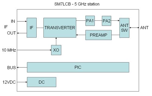
The following functions have each block in the transverter:
- IF is the IF switch for 144 MHz IF used in my transverter system.
I use this because all my transverters is cascade connected so I only have one IF cable up to the antennas. - TRANSVERTER is a DB6NT with input for external LO.
- PA1 is the first stage power amplifier which will take the output of the transverter 200 mW.
The PA is marked with 300 mW in and 4.8 W out. Will see what it will give. - PA2 is the second stage power amplifier which take the output of first stage and maybe give 25 W output, we will see.
- PREAMP is a DB6NT 1 stage preampifier with NF less then 1 dB.
- ANT SW is a SIVERS LAB (Philips) koax realy with SMA connectors.
- XO is a DB6NT local oscillator (117 MHz) with 10 MHz locking.
- PIC is home made controller of the transverter.
It use ICOM bus connection to the controler of the receiver system.
It control the IF-switch and supervision of output power, temperature etc.
TX-control is via DC level on the IF coax (+DC at TX). - DC block is handling DC-switching controlled by the PIC for PREAMP/PA etc.
New direction autumn 2011
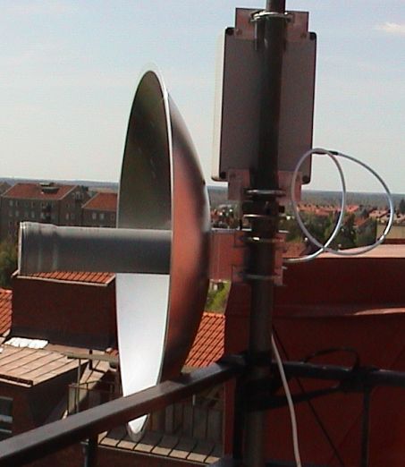
Well I didn't got time to finish the 6 cm transverter before summer 2011. Mostly because we changed QTH in Stockholm so during spring 2011 all radio equipment was packed and stored for the move. The during summer 2011 I start thinking about how to integrate the 6 cm transverter into my antenna system. My first ideer was to combine 6 cm with my 3 cm into my 90 cm dish. On this dish I today have a feeder for both 6 and 3 cm. But then I changed my mind. I will now integrate 6 cm together with 23/13/9cm into my 1.9 m dish. For that reason I during the autumn 2011 purchased a four band feeder for this antenna e.g. a feeder for 23/13/9/6 cm see picture below. Why I changed my mind? Well 1.9 meter is bigger then 0.9 meter and I have a project there I will combined 3 cm with 24 GHz with a new feeder which I purchased from Denmark during 2011, but that is a completely different project.
Four bad feeder for 23/13/9/6 cm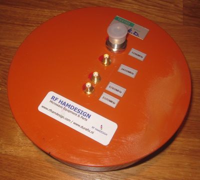 | 10 and 24 GHz feeder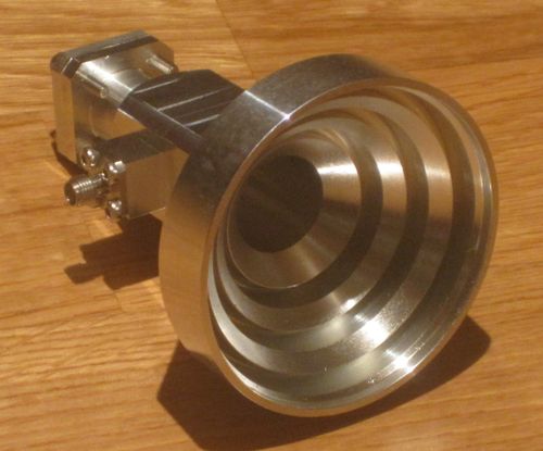 |
Work during 2015
During the end of the spring 2015 I started to work on my 6 cm transverter again. I have now started to mount the parts in the outhouse box and also made some CPU controller and power switching. But when summer came it was still to much to make on the transveter so I have to pause during the summer hoping to start the build in end of the summer. But that didn't happened so now I have to restart the project again. Here are some photo of the project.
PA mounted in box.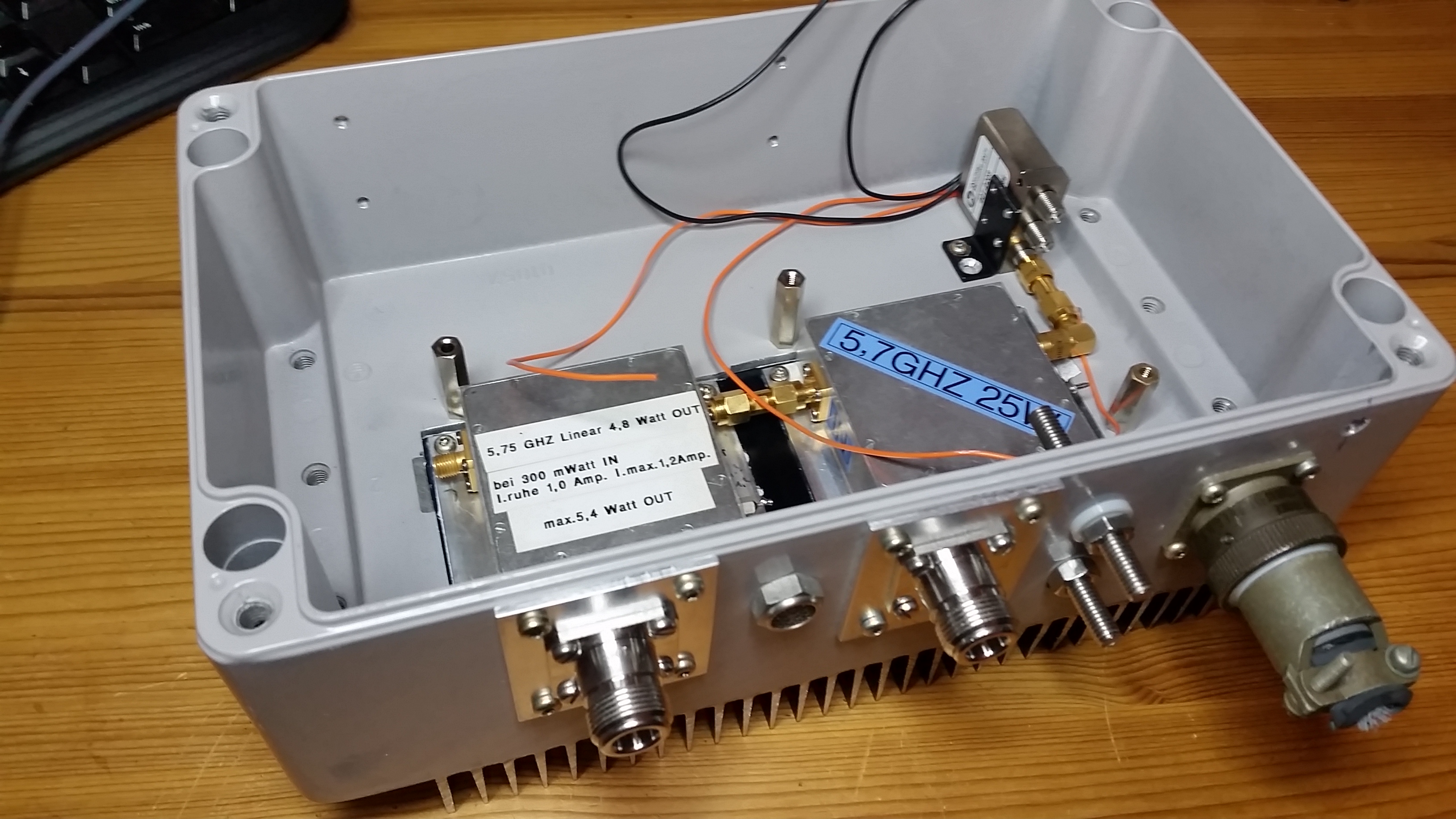 | Heatsink and connectors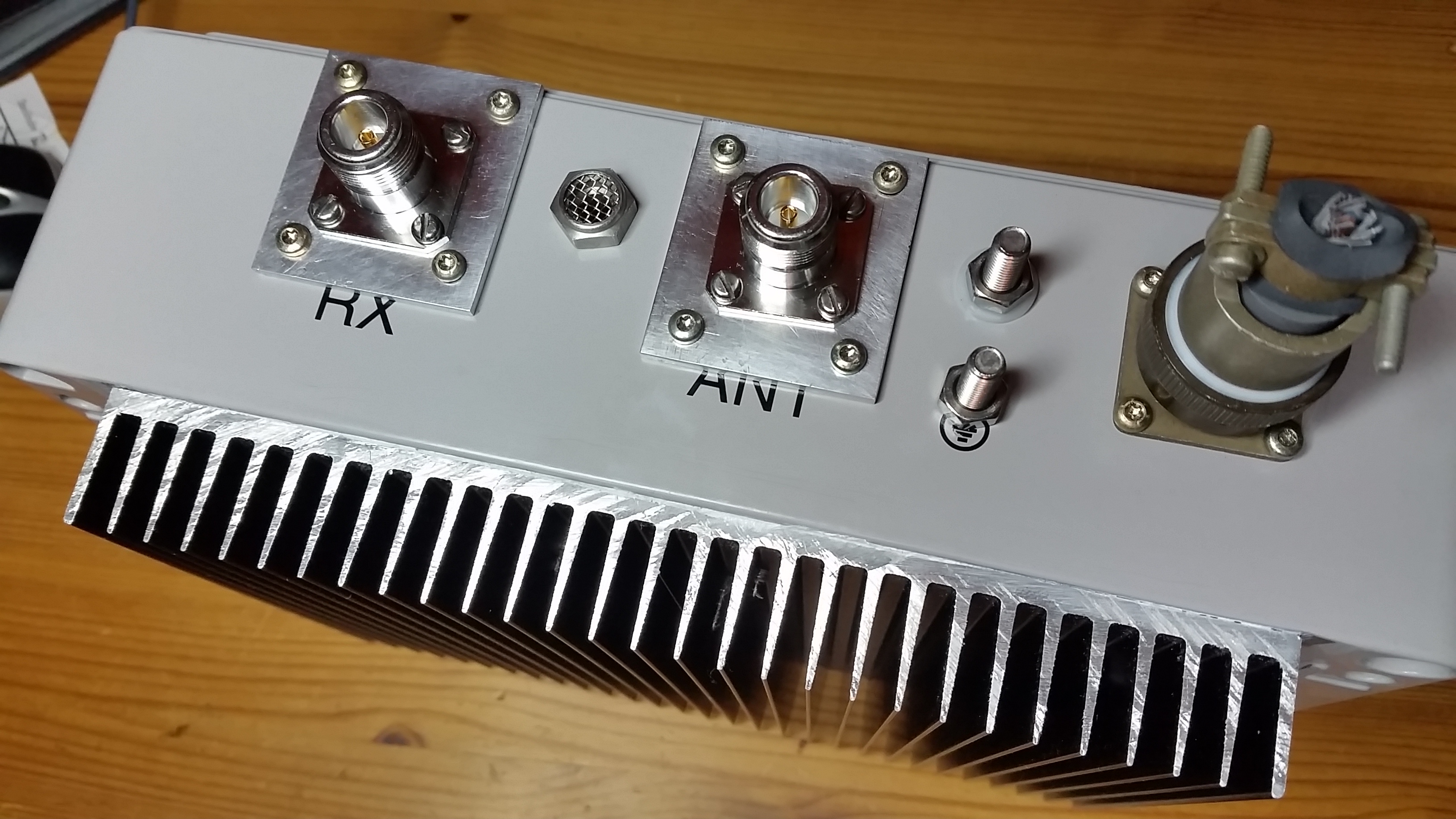 |
more will come...
| SM7LCB |
End of this page
|
 |