| Last updated 2025-04-23, UNDER CONSTRUCTION. | Back SM7LCB remote page |
Table of contents
- Overview
- Computer Module
- Audio Interface
- IC-706 Interface
- ICOM Bus Interface
- CW/PTT Interface
- Driver Output Interface
- Analog Input Interface
- ddd
- ddd
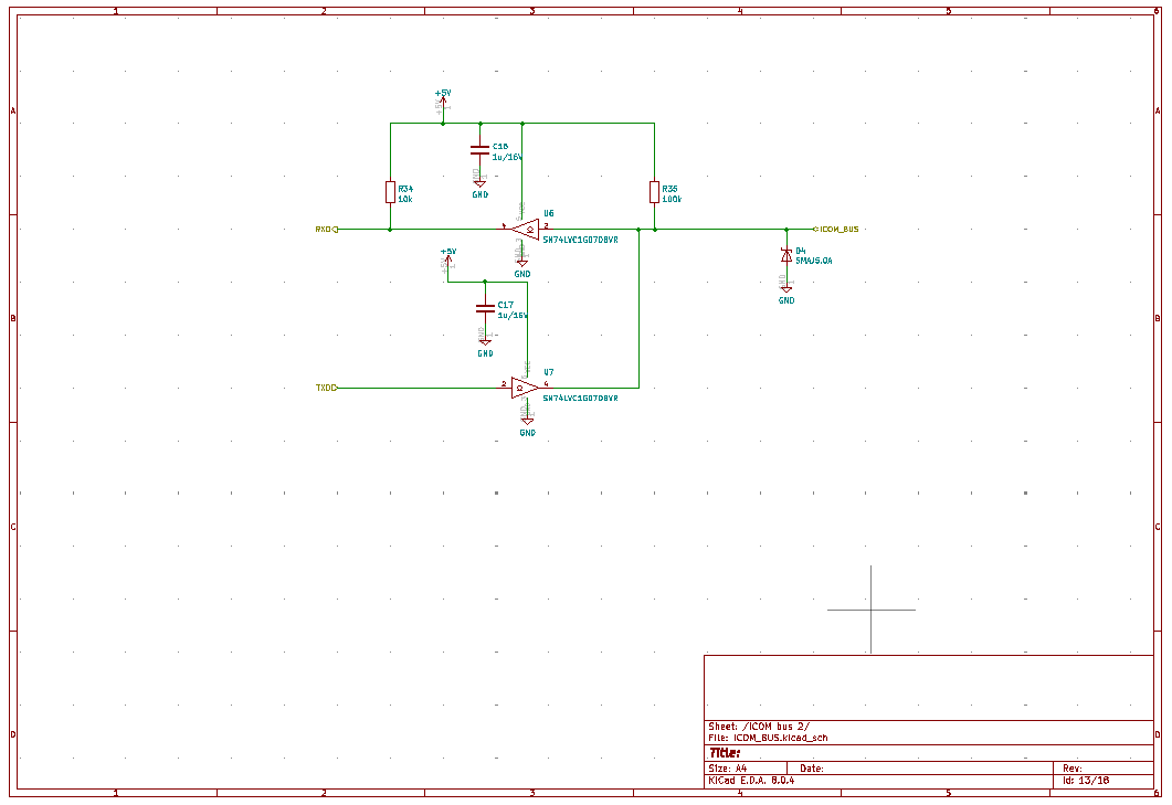
Overview
Since I updated my remote QTH with the 2010 years server
this server have been running nice with one failure when the power
supply stopped working and a new was installed. But after 15 years of
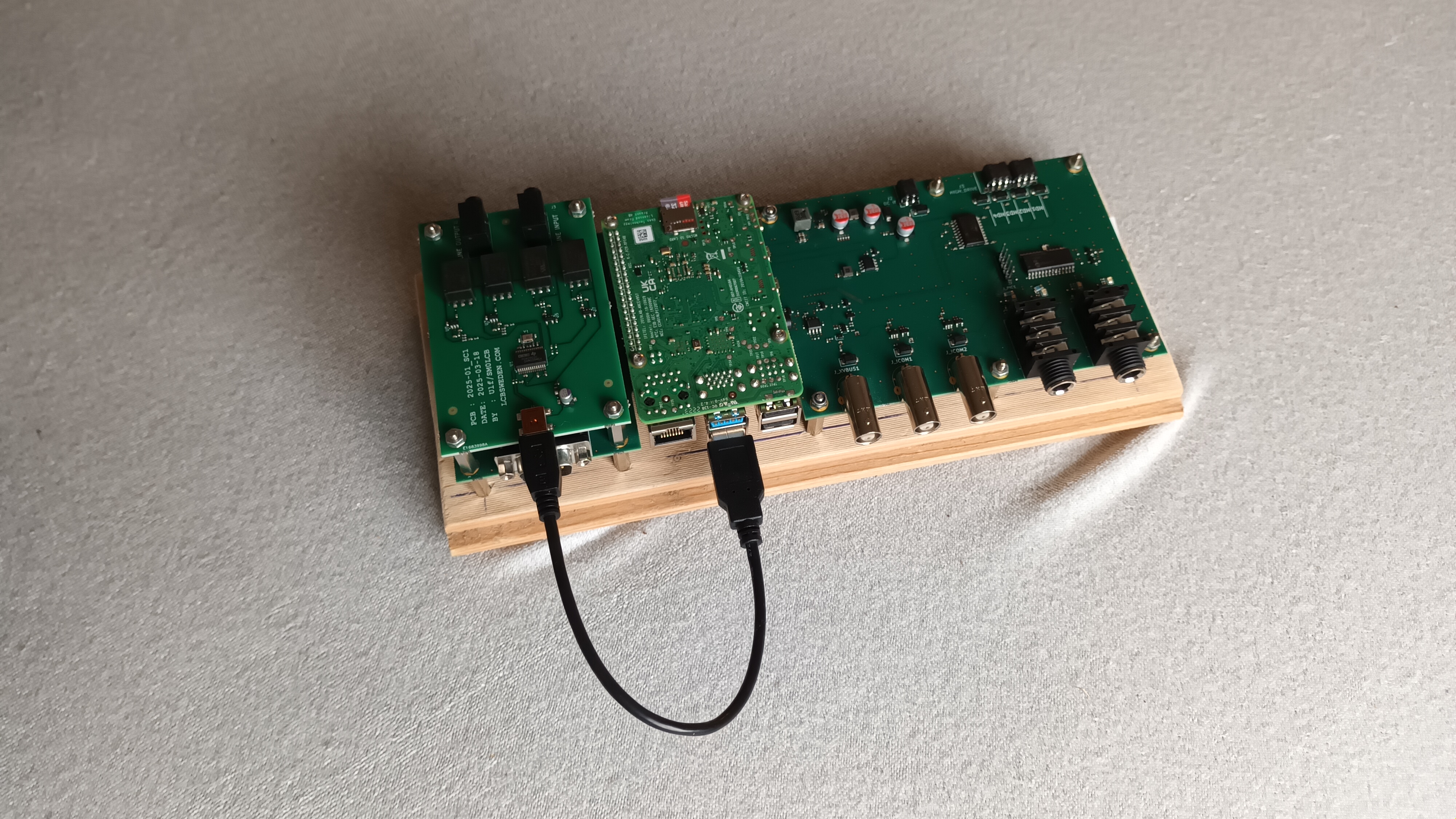
operation it was time the replace it with a new server.This time it was time for me to explore the Raspberry PI computer modules and when I started this exploration the state of the art was the Raspberry PI module 4B. But to get a good server there need to be a lot of interfaces which for the 2010 server was external units expanding the mini-ITX computer. So with the Raspberry PI module it was time to integrate all this interface to a base board there the Raspberry PI module and be a onboard computer so a hardware design was stared using the KiCad software and when ready to be build it was send to Eurocircuits (not cheep but good supplier for complete PCBA). The result is in the picture below,
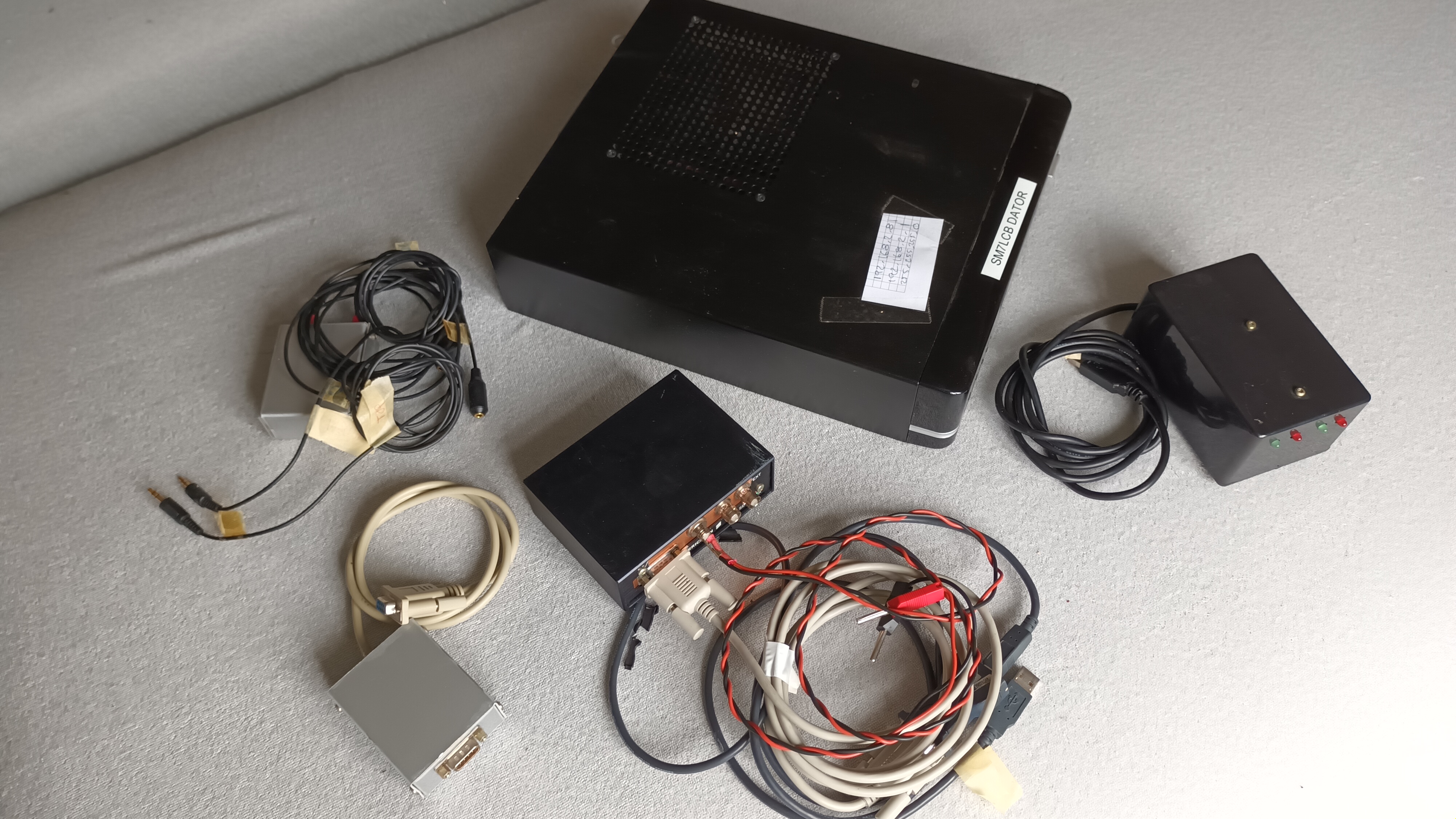
This is a big change from the previous radio server with all the external interfaces and cables. The old server look like this compare with the picture above. Note that for both servers the power supply cables and cables to connect the the radio station is excluded on both pictures.
Computer Module
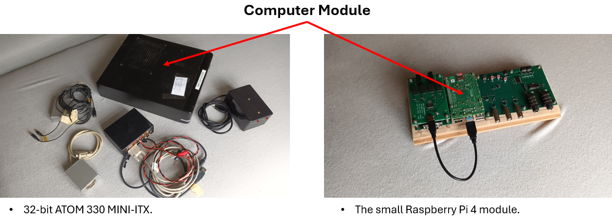
The computer (module) is the core of the radio sever running the different server application for making it a radio sever. The previous computer has a main board of mini-ITX size with an Intel Atom 32-bit CPU. That is now replace with the popular Raspberry Pi 4 computer module. This module have different interfaces which is used in this server application as,
- GPIO, for output drivers, IC-706 control and fan control.
- UART, for serial communication with IC-706, two ICOM bus, new XV-bus (current) and CW/PTT control.
- I2C, for communication with external ADC-converter.
- USB, for connection with an audio board for line input and output (not so good on the module itself).
- Ethernet, for connection the the local network and internet.
Audio Interface
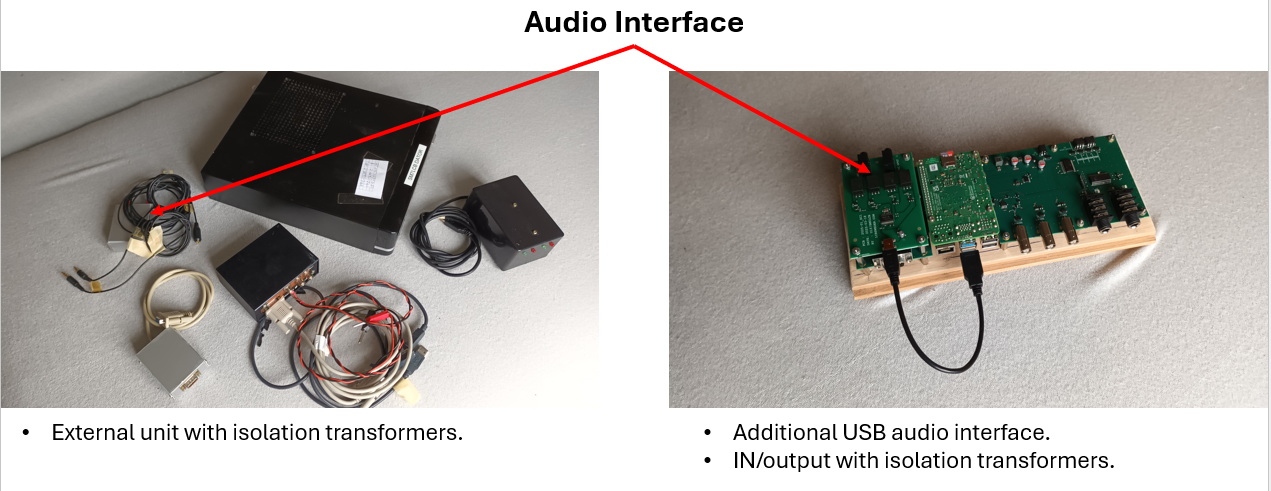
The old server have built in audio interface with line input and output. That is not the case for the Raspberry Pi 4 and when searching for a external USB audio interface I did not found any good for line input and output. So I made an small audio interface board which can be mounted on the main radio server PCBA. It have a IC preforming the audio to USB handling and all powered for the USB port. As I have isolation transformers on the previous server I wanted the same here so the audio PCBA have isolations transformations on both input and output line input which is using standard TRS 3.5 mm jacket.
Schematic of PCBA.
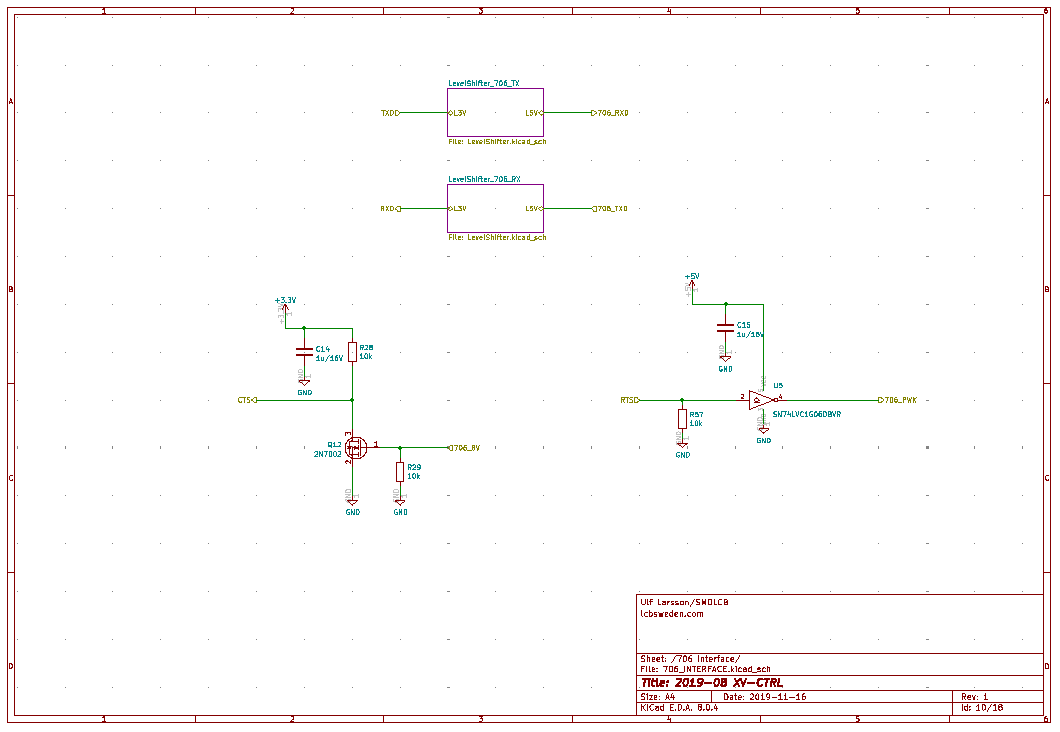
IC-706 Interface

The remote head interface for the ICOM IC-706 are similar on both version with an DB-9 connector as cable connection to the radio head connector on the radio part.
Schematic (draft).
One external part excluded for the hardware list as the interface now is integrated on the server PCBA.
ICOM Bus Interface
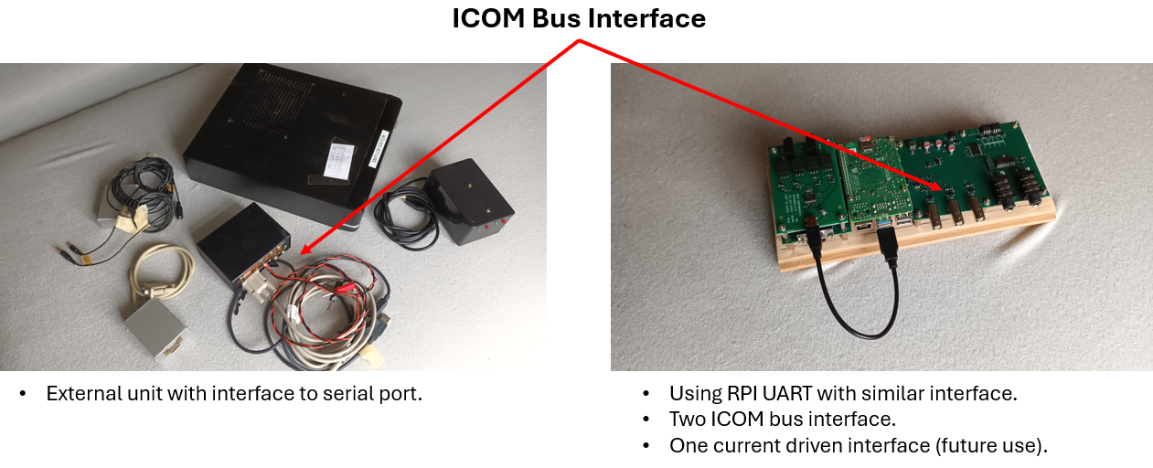
The ICOM bus have been used for both controlling the connected ICOM radio (IC-706) but also antenna control and transverter control as it have been since start of the remote operation. The old server have only one bus port connector but with the new server PCBA I have extended it to two interfaces so one can be dedicated to ICOM radio and the other to antenna and transverter control.
Schematic.
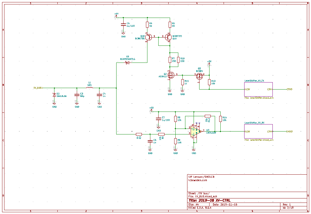
There is also a extra bus interface called "XV-Bus" on this PCBA. This is a more robust interface which is a copy of the SK2W with some minor modifications. Currently not used but maybe it will be used when making new controllers for antenna and transverter control.
Schematic.
So again one external part excluded for the hardware list as the interface now is integrated on the server PCBA with more interfaces.
CW/PTT Interface
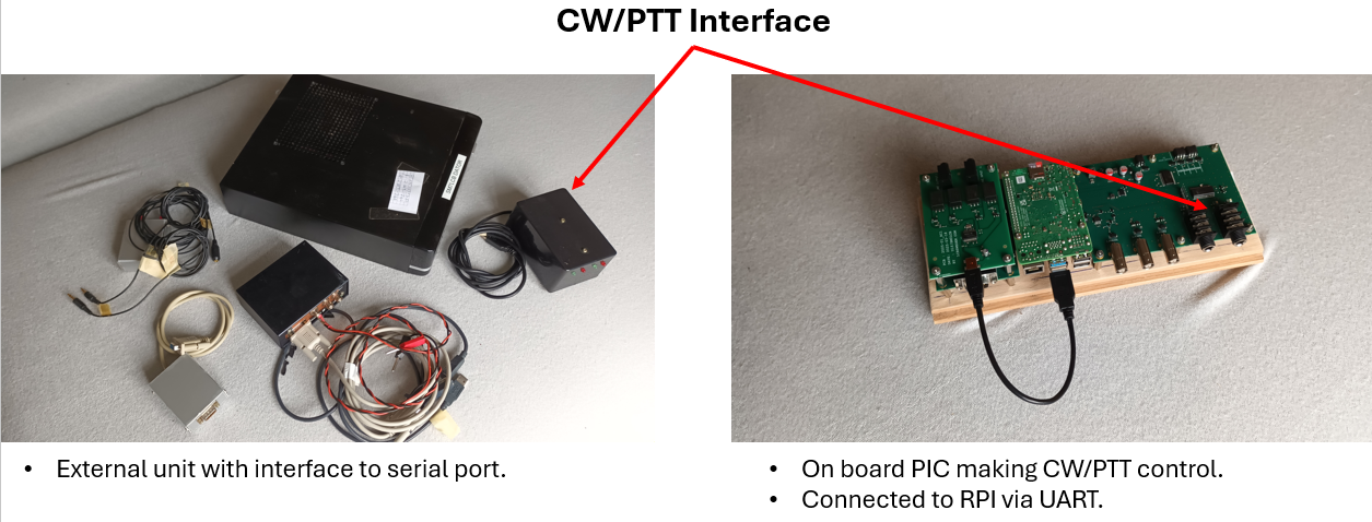
The CW/PTT interface is according to my own solution. It is a small PIC controller which can control to radio stations with CW/PTT signals and have a serial interface to the computer. The old server have an external box which was connected to computer via USB-cable but now this solution have moved into the server PCBA.
Schematic.
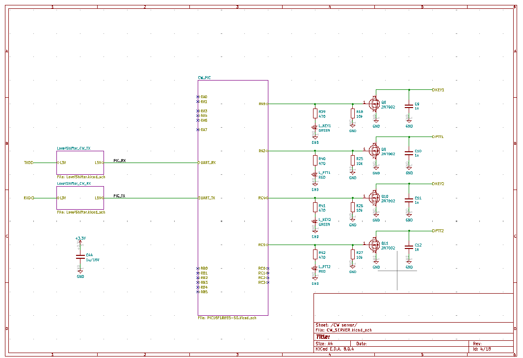
One external part excluded for the hardware list as the interface now is integrated on the server PCBA.
Driver Output Interface
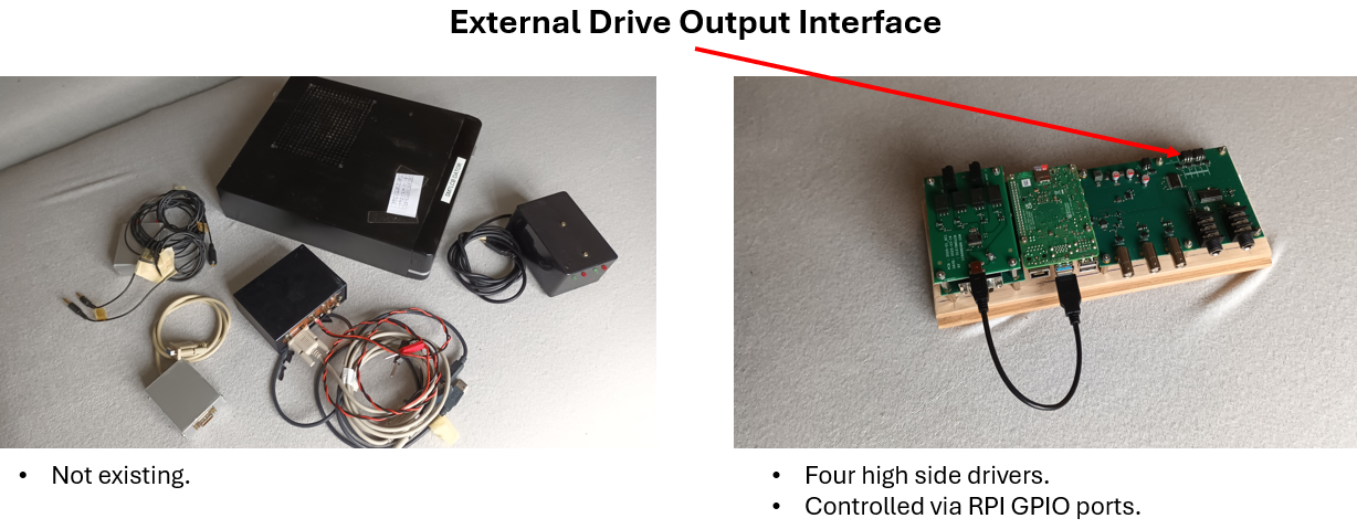
This interface was missing in the old server but there was some need to have it so therefore it have been integrated into the new server PCBA. The current implementation is giving four high side drivers there each output can drive at least 1 A and have short circuit protection. From software point they are controlled as normal GPIO pins.
Schematic.
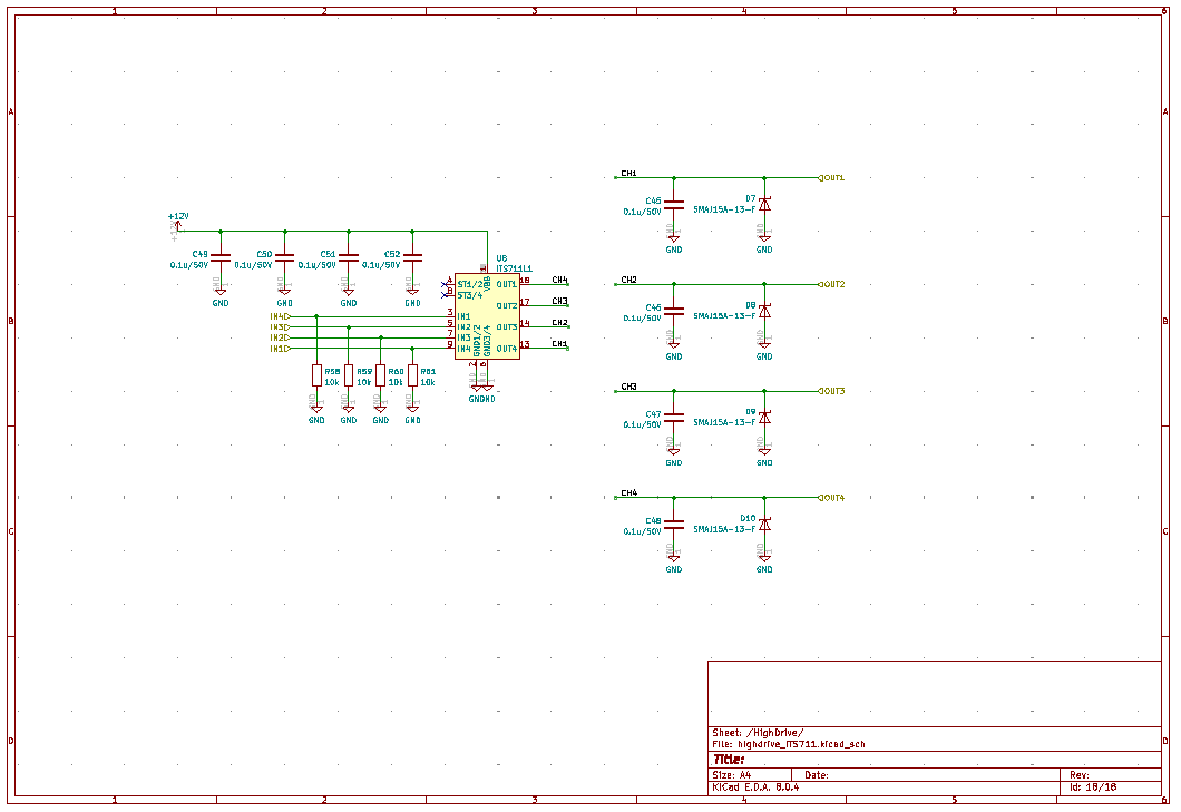
Analog Input Interface
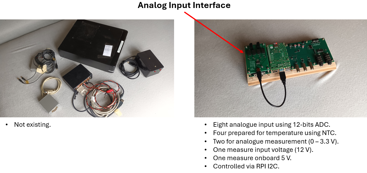
This interface was missing in the old server. It was added to the server PCBA for easy measurement of analog signals and most important was temperature measurement. For temperature measurement the solution was to use 10 kohm NTC resistors as sensors. Maybe other similar sensors as PT1000 or any PTC can be used if the software is adapted to that. Some ports do not have the pull-up resistor of 10 kohm to 3.3 V and can then be used to measure any voltage if adapted to the input voltage range of 0 - 3.3 V.
Schematic.
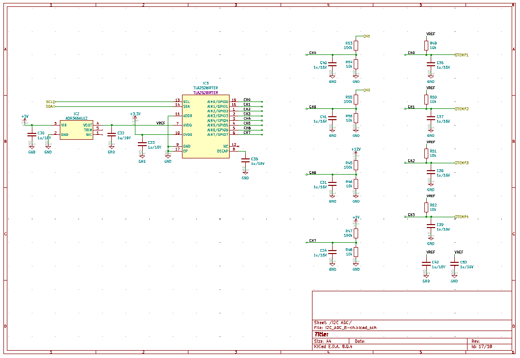
| SM7LCB |
End of this page
|
 |