SM7LCB - 10 GHz station
Last updated 18 December 2010.Hi, and welcome to my page regarding my 10 GHz (3 cm) transverter. The content is:
- Combined 5/10 GHz
- 10 GHz - 0.5 Watt
- 10 GHz - 5 Watt
Combined 5/10 GHz
This transverter was from the beginning built for both 5 and 10 GHz in same box.
You can read more about it on my 5 GHz page. The photo below show both transverters and the antenna switching.
10 GHz - 0.5 Watt
Well it didn't when well with the combined transverter so I decided to add more power and only have 10 Ghz in the unit.
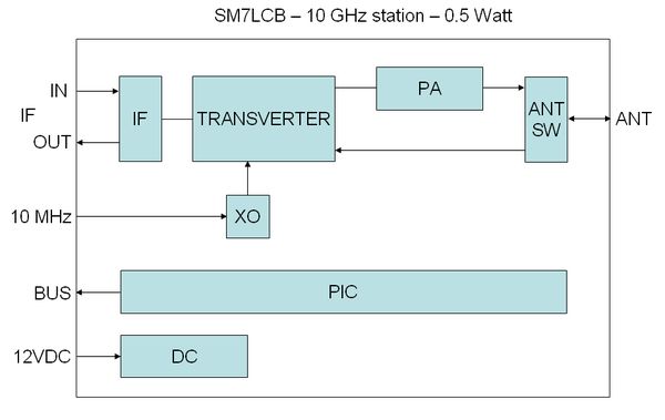
The following functions have each block in the transverter:
- IF is the IF switch for 144 MHz IF used in my transverter system.
I use this because all my transverters is cascade connected so I only have one IF cable up to the antennas.
This IF switch also have the RX/TX switching between the RX and TX path of the transverter. - TRANSVERTER is DB6NT with external LO input.
- PA this is a LA6LCA with 0.5 Watt output at 1 mW input therefore an attenuator between transverter and PA..
- ANT-SW is a nice SMA relay.
- XO is a Ericsson 10 MHz locked X-oscillator modified for 96 MHz.
- PIC is home made controller of the transverter.
It use ICOM bus connection to the controller of the receiver system.
It control the IF-switch and supervision of output power, temperature etc.
TX-control is via DC level on the IF coax (+DC at TX). - DC block is handling DC-switching controlled by the PIC for PA/PREAMP.
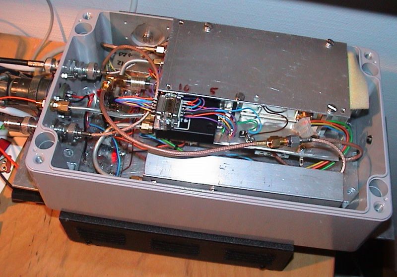
The transverter is build in an Ericsson (filter/preamp) unit for mast mounting.
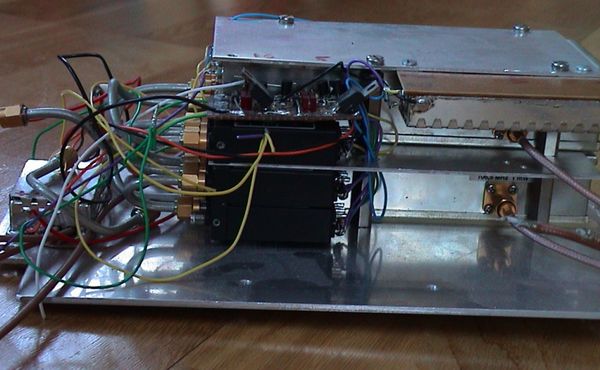
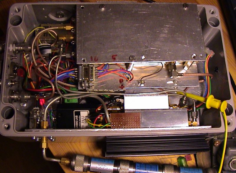
 | Top deck is transverter, antenna relay and D-SUb for interconnection. Low deck is to left 12 to 24 VDC converter (inside box), DC distribution board (with P-MOSFET), PIC microcontroller and under the transverter is a R&S 10 MHz oscillator. |
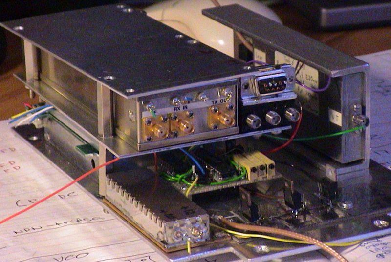 | Same as above but here you also see the 0.5 Watt PA. |
 | Smoke test of the transverter with a wire antenna. |
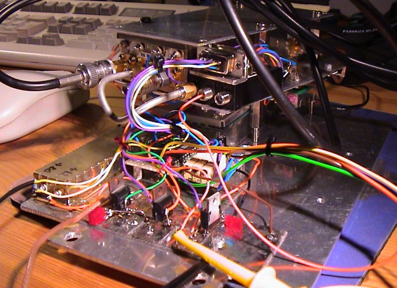
 | The transverter mounter inside the box with all wires in place. See the attenuator at transverter TX output. |
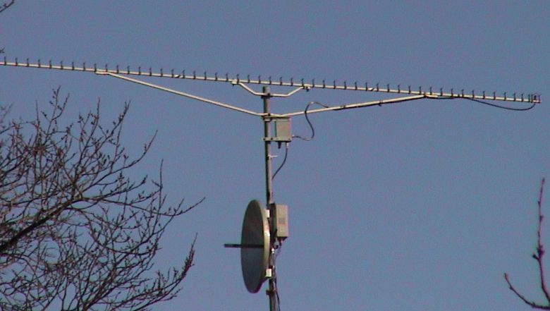
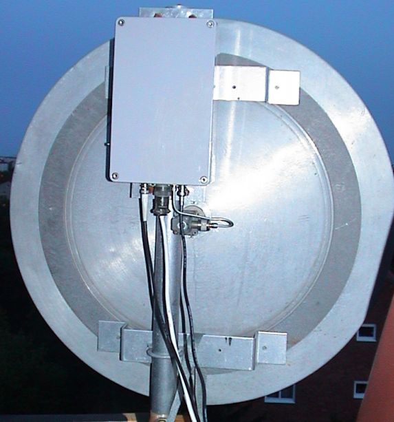 | Testing of the transverter together with the antenna in Stockholm. |
10 GHz - 5 Watt
Okay 0.5 Watt is more then 0.2 Watt but I notice that more power is needed on 10 GHz for good DX.
So I invested in a new 5 Watt power amplifier. Now I see that I should have gone for at least 10 Watt! Maybe next step?
I also added a preamp and thats good.
The following functions have each block in the transverter:
- IF is the IF switch for 144 MHz IF used in my transverter system.
I use this because all my transverters is cascade connected so I only have one IF cable up to the antennas.
This IF switch also have the RX/TX switching between the RX and TX path of the transverter. - TRANSVERTER is DB6NT with external LO input.
- PA is a DB6NT with 5 Watt output at 200 mW input.
- PREAMP is DB6NT.
- ANT-SW is a nice SMA relay.
- XO is a Ericsson 10 MHz locked X-oscillator modified for 96 MHz.
- PIC is home made controller of the transverter.
It use ICOM bus connection to the controller of the receiver system.
It control the IF-switch and supervision of output power, temperature etc.
TX-control is via DC level on the IF coax (+DC at TX). - DC block is handling DC-switching controlled by the PIC for PA/PREAMP.
 | Here is the new block which shall replace the previous 0.5 Watt amplifier. from left the interconnection (D-SUB), antenna connector, antenna relay and finally the PA (below) and the PREAMP (top). the brown board is temperature sensor for the PA. |
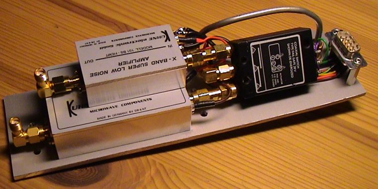 | Same as above but from the other side. |
 | The module install into the transverter box. |
 | The module install into the transverter box. |
 | In the spring of 2005 the transverter was QRV from Öland. |
If you want any more information on this page, send an email to me. For address see main page.
| SM7LCB |
End of this page
|
 |