| Last updated 31 January 2007. | Back SM7LCB remote page |
Presentation
When talking about remote control of a radio I always have
been looking for the “front panel at home solution”. I like to see the radio and
feel it as it where a local radio. I have not find any GUI program with the same
feeling so therefore the main task when I wanted to remote control the radio
where to find a way to get the front panel in front of me.
At the time I started looking for a radio with the possibility for “front panel at home solution” I only have a single chose, the ICOM IC-706. Not the easy nice front panel but still it has the possibility to remove the front panel from the radio and remote control it via 3 meter of cable. Could I maybe extend this remote control to 500 km via Internet?
When I bought my first ICOM IC-706 (1996?) I also got the service manual so I could investigate the possibilities. I also bought the remote cable, which I quickly cute in two pieces and added normal D-sub connectors to the unconnected parts. With the manual and the cute cable I tried to extend the remote capability for the ICOM IC-706.
In 2000 have an operational remote solution for the ICOM IC-706 running with software for Linux in both ends. Until 2004 I were try the remote control by using my local station with local remote control in my small shack. Finally it got operational with my remote station on Öland during summer 2004 and that software is still running.
NOTE
Sorry that the software still is not in place here on the web page.
I'm in the process of rewriting my code for an open source async library (part of SvxLink).
Then that is finished and working I hope to get it on the web (during spring 2007).
Remote Cable
If you look into the manual of the ICOM IC-706 you will find following information for the connection between the front panel and the radio part.
| Pin | Name | Description |
| 1 | LRXD | Data transfer from front panel to the radio. |
| 2 | LTXD | Data transfer from radio to the front panel. |
| 3 | 8V | DC power (8V) to the front panel. |
| 4 | AF | Output audio to headphone jacket. |
| 5 | GND | Data, power, output audio and power control ground. |
| 6 | MIC | Microphone input. |
| 7 | MICE | Microphone input (ground). |
| 8 | PWK | Power control (switch ON button). |
Obviously there is possibility to remote control the radio when you see the LRXD and LTXD control lines. So I started to check the signals on this lines with my cute cable. I found quickly that this is an ordinary asyncron serial data transfer link using the following parameters.
| Parameter | Value | Description |
| Level | TTL-level | There is a need for a RS-232 adapter before connected to any computer. |
| Speed | 19.2 kbit | No problem. |
| # bit | 8 | No problem. |
| # stopbit | 1 | No problem. |
| Format | xfe…xfd | Similar to the ICOM bus CIV but only one starting character (0xfe). |
I now know that it will be possible to remote control the front panel via computers. One nice thing with the front panel is that it universal front panel for anything you like to control if the display, buttons and turning wheels are fine. The protocol between the front and the radio don’t have anything to do with radio control. The protocol only send information from front panel to the radio about which button or wheel you pushed/turned, no radio information. From the radio to the front panel there is only display information with the limitation for that the display can show. So you can build a program using the front panel to control you antenna rotor or signal generator. But the complete listing of the commands to/from the front panel have I still not written down, somebody done that?
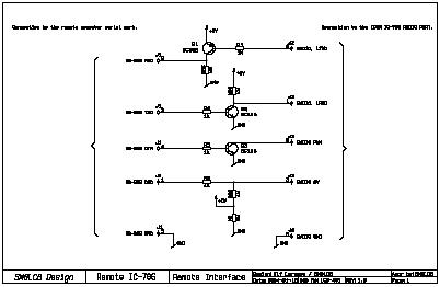
Hardware remote site (at the radio)
To start up the radio you need to push the POWER button on the front panel. This will send a ground the PWK signal to the radio part. When doing that the radio will start up and the display will get the power via the 8V line. How to do this remote from the other end? There are many ways to solve it but I used the DTR and DCD signals on the serial port because I will anyway use it to transfer the control data. I did the following connection to the serial port (assuming a D-sub 9-pol serial connector).
| Pin | Name | Function |
| 1 | DCD | Power detection from the radio of the 8V line. |
| 2 | RXD | Data transfer from radio to the front panel on the LTXD line. |
| 3 | TXD | Data transfer from front panel to the radio on the LRXD line. |
| 4 | DTR | Power control to the radio on the PWK line. |
| 5 | GND | Ground signal. |
These are the only lines I use in the cable into the radio part. All audio connection is done via the radio backside connectors (line in and speaker out). The picture below will show a real schematic how to build this interface. Click on the picture to get the PDF-file. The interface is build using cheep transistors and resistors. Of cause it can be built with nice RS-232 interface circuits but why?
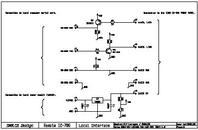
Hardware local site (at the front panel)
At the front panel the hardware set up is easy. I have wired the RXD and TXD signals for transfer control data to the radio part. There is also a way to detect a press on the POWER button via the serial connector pin DCD. Currently I’m no using this connection to the POWER button. Table below show the serial port pin used to connect to the front panel (assuming a D-sub 9-pol serial connector).
| Pin | Name | Function |
| 1 | DCD | Power button detection of the PWK line. |
| 2 | RXD | Data transfer from front panel to the radio on the LRXD line. |
| 3 | TXD | Data transfer from radio to the front panel on the LTXD line. |
| 4 | GND | Ground signal. |
These are the only lines I use in the cable into the radio part. All audio connection at the front panel is done directly between headset and the computer. If you want easy PTT function of the radio you can connect a microphone to the front panel. When pressing the PTT button on the microphone this will be detected in the front panel and sent as a data telegram over the serial connection. The picture below will show a real schematic how to build this interface. Click on the picture to get the PDF-file. The interface is build using cheep transistors and resistors. Of cause it can be built with nice RS-232 interface circuits but why?
.
The software
Now we are finish with the hardware. Now we need to connect these separated parts of the radio via Internet. For this purpose we need some software programs see picture below. At the remote site we need a serial connection from the radio part of the IC-706 to a serial port on a computer. On the remote computer there will be a server program, which will connect to the radio part via the serial port and start listen on a TCP/IP port number on the Internet side. The server will be running waiting for a connection from the local site and a client program running on the local computer. This local program called the client program will at start connect to the remote server via the computer name/IP-address and the active port number. It will also connect the local serial port to the IC-706 front panel. And then we have a remote controlled IC-706 using its normal front panel, simple and easy to do.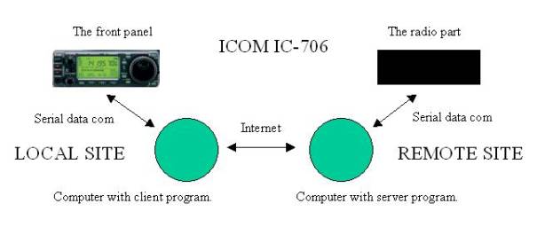
Software remote site
My first test with remote control front <-> radio via computer where done on a single computer with two serial ports. I made an easy program in C (Linux) which tunneled the serial data between the to parts and the remote control via computer work nice. I didn’t use the POWER on button on the front panel. Instead the program did the start up of the radio at program start.When I then rebuild the software to tunneling the serial data between two serial ports on two computers I did get some problems during start up of the radio. The problem was that the radio started but very quickly it switched off. I started to look into the problem. Quickly I notice that the front panel is sending a “keep alive” message to the radio every 100 ms from the time the front panel get power. Because of this “keep alive” message at power on, which didn’t come in time to the radio from the front panel the radio fast switch off the power. Why it didn’t come in time, because of processing timer from front panel via the connected computer to the radio.
So the server program, which handles the radio connection, need to have a nice start up procedure and also a “keep alive” function. The table below show the state for the server and what to do in each state. The “keep alive” message is a simple message with 4 characters, which in hexadecimal codes will be “xfex0bx00xfd”.
| State | Name | Function |
| 1 | RADIO_OFF | Deactivate
the DTR line (PWK signal to the radio). Wait for power on command. Activate the DTR line (PWK signal to the radio). |
| 2 | RADIO_GO_ON | Wait for the DCD line to indicate 8V from the radio when go
to RADIO_ON. If timeout (1 second) when go to RADIO_OFF. Deactivate the DTR line (PWK signal to the radio). |
| 3 | RADIO_ON | Send
the “keep alive” command to the radio every 100 ms. Wait for the radio power off command when go to RADIO_OFF. If the DCD line indicates no power when go to
RADIO_OFF.
|
I have implemented this (and some more states) in my Linux
ICOM IC-706 server. This program will take some argument with information about
the used serial port for the radio and also which service port number it will
listen for TCP/IP connection.
sm7lcb@linux:~>
./icom706Server -?
Usage : ./icom706Server -p
-i -d -k
-p my
server port number [23020]
-i use
icom radio on device [/dev/ttyS0]
-d
enable debug text output
-k
enable stdin debug
So to start up the server using the Windows COM1 port and listen for connection on port number 12000 the command will be like,
sm7lcb@linux:~ >
./icom706Server -p 12000 -i /dev/ttyS0
Icom706Server started on
port 12000
Icom706Server connecting
device /dev/ttyS0
Now the server is running listen for connection on port number 12000 and will use the serial port /dev/ttyS0 for communication with the radio part of the ICOM IC-706. Note that this program will automatically start up the radio when it gets a connection on the port number 12000. When the last connection on this port number is disconnected the server will power off the radio.
Hopefully I will make this Linux program available on this site when I have clean up some parts.
TOP
Software local site
The program at the front panel will be very easy. It will in principle at program start connect to the server (starting the radio if not started) and also connect to a local serial port there the front panel is connected. Incoming data from the front panel will then be sent via the TCP/IP connection to the server side at least 10 times a second. In the other direction the program will take the incoming TCP/IP package and take the serial data and send it to the front panel.
Currently I have to types of program, which can do this. The first program is a Linux only program similar to the server program and the second one is a simple python script with which it’s easy to use a Windows computer at the front panel site.
Linux client program
Linux version can be used in this way. Hopefully I will come back with software for this program also here on the web.
sm7lcb@linux:~>
./icom706Client -?
Usage : ./icom706Client -s
-h -p -i -m -d -k
-s
<my server port number>
-h
<connect server name/ip>
-p
<connect server port>
-i
<use icom front on device>
-m
<use audio mixer device>
-d
enable debug text output
-k
enable stdin debug
Windows client program
The python script is maybe more clear to use.
Here you find the python script. The program has been developed using Python 2.3.3 and using the serial class USPP. For more information about installation and finding the needed software see my Python page (when ready).
| SM7LCB |
End of this page
|
 |