| Last updated 21 October 2007. | Back SM7LCB remote page |
Presentation
This page will present my way of running remote CW operation. The problem were how to use normal paddle for keying a remote station via Internet. To send CW generated by text memory or key input on a keyboard is not so difficult. By I wanted to have the paddle to do the CW operation to get better felling of the CW operation even if running a remote controlled station.
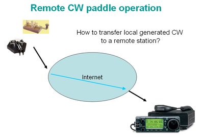
Easy will many people say. Just key a tone and send it over a IP-phone solution and add a tone decoder at the remote site. Yes that will make it but I like a "digital" solution to include good PTT control and also have minimum data transfer over the connection. Hope to tell you how I did it on this page.
Sample the CW
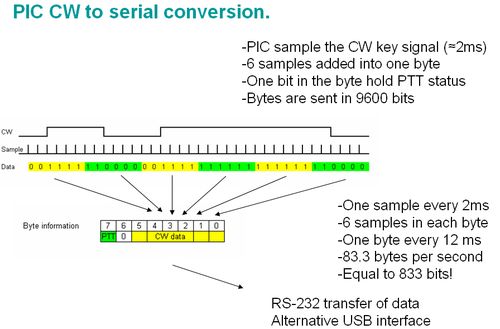
First I need to transfer the keyed CW at my
local site to the digital world. I did this by sample the
generated CW code with about 2 ms interval. Sex of
these samples are collected into a data byte. I use the high bit
in the byte to indicate the PTT status. That left one bit in the byte
unused for future extension/improvement. This byte of data is then sent
to the remote site and there decoded in the opposite way. This make a
nice solution for sending "bad"/"good" generated CW code from one site
to other site.
Version 1 (only Linux)
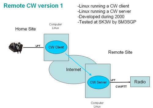
First version were developed from a Linux CW server I develop for transmission of CW text message from my log-program (LOGGER). This CW server were build in two parts a Linux driver for CW generation and a CW server running user space. This CW sever application were extended to include this sample and transfer of the sampled data over a TCP/IP connection between the client and the server, see picture below. Even if they are named client and server the same CW server code were used in both ends, only start parameter set the operation mode for each end. This solution have been tested and used by Gunnar/SM3SGP during remote operation of his contest station SK3W.
Version 2 (Linux server)
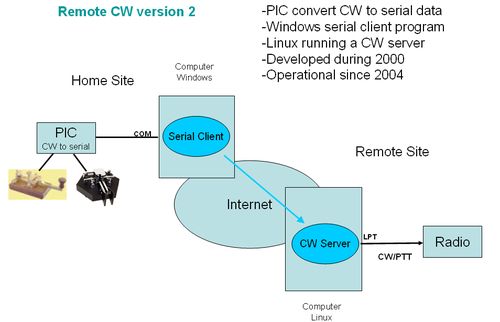
In beginning of 2004 a started to code a
small microprocessor (PIC controller) to do the sample of the CW code
at client side. With this hardware part I was able to run remote CW
operation from a Windows computer. The hardware, named CW PIC, sample
the CW code and sent data as ASCII code to a serial port on the
Windows/Linux computer. I made a small python script which made the
TCP/IP connection to the server simulating the version 1 Linux client.
This client application transfer the sampled data over Internet to the
remote site. At the remote site I still used the Linux CW server from
version 1. This operation have I used when running CW operation from my
remote station SM7LCB. It have been running very nice and it seems most
people can understand my CW so fare?
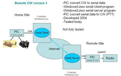
Version 3 (Windows/Linux)
When I in 2004 coded the CW PIC I also added the possibility to send the sampled data into the CW PIC to generate CW code e.g. a replacement of the CW server device driver! Until beginning of 2007 this feature haven't been tested. When it was time for the SM5QA microwave meeting in Stockholm it was time to clean of the dust from this feature. People have started asking how I did my remote CW operation and most people don't like to run Linux on remote site so therefore this version where needed (for my own use there will still be a Linux server at my remote location). The concept here is to have a small server running the remote site which can take a connection from my version 1 Linux client or version 2 python client and transfer the data to the serial port and into the CW PIC for CW generation.
During this development I develop a single client/server program which shall be able to run on both Linux and Windows. The hardware in the CW PIC differs a lite from the client side and the server side but both use the same program code. So if you program on CW PIC microprocessor it can run as client or server deepening on the hardware around it and the connection to the computer.
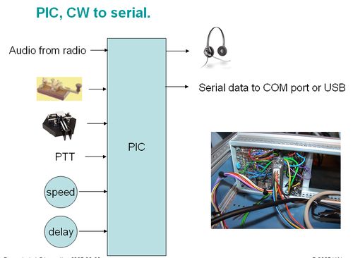
Hardware CW to Serial (local/client)
At the local/client site the hardware part is bit complicated. On this side we need several input and output for easy CW operation. Within the CW PIC there is an integrated electronic keyer. Not the best one but still useful. If you prefer to use you own keyer there is a input for that also which make it easy for everyone to use the CW PIC for sample the CW code. There is also needs for audio interface because of the nature of remote operation the monitor CW tone need to be generated and switch in to your audio path on the local side. Without this switching it will be very difficult to send CW by listening to the monitor signal from the remote side. Of cause there is also a need for the serial port connection and power to the unit.
For complete schematics click on picture below.
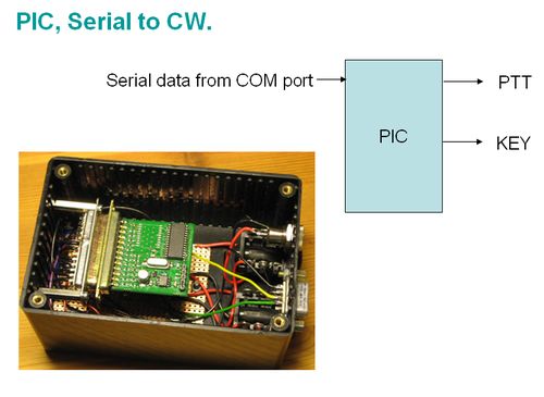
Hardware Serial to CW (remote/server)
At the remote/server site the hardware is easy. I serial port interface for connection to the computer. As output were will be two lines PTT and CW. It you use open collector, relay or opto-coupler interface for these lines is up to the user. Yes power is needed also.
For complete schematics click on picture below..
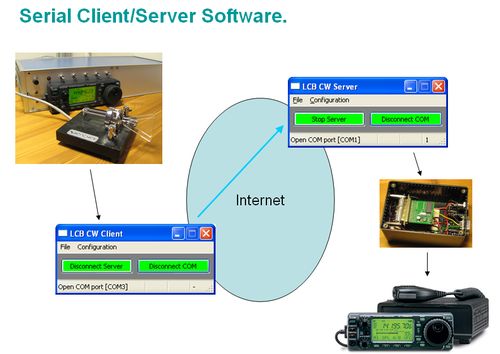
Software GUI (Windows/Linux)
The software for client and server operation together with the CW PIC hardware is developed with Dev-C++ compiler under Windows using wxWidget GUI framework. Both Dev-C++ and wxWidget are free to use software tools and is easy to use. By using the wxWidget GUI framework the code shall be possible to compile and run under both Windows and Linux. Maybe even Mac OS if serial port communication package will be found for Mac OS. Current serial port package don't support Mac OS.
The software is a general serial port transfer program between the client and the server. The CW client and the CW server is only two of the possible selection of operation for this program. Hopefully it will be able to support other serial port remote operations needs also.
For more information about this software please click on picture below.
Software none GUI (Linux)
Not ready yet!
Software CW PIC
The hardware
schematics for the CW PIC are available on this page. The used
microprocessor PIC16F876A needs to be loaded with the CW
PIC software. You can download the software in a hex file format,
see table below. This file is ready to download to the microprocessor
chip with a PIC programmer.
| Date | Version | Remark | File |
| 1 Maj 2007 | 1.0 | First released version (still a development version). | LCB_CW1_V1-00.hex |
| 21 October 2007 | 1.4 | Fixed several errors in the code. Added better communication together with wxLcbSerialNetwork. |
LCB_CW1_V1-4.hex |
To program the microprocessor you need a PIC programmer. These can be built or you can buy them. Software and hardware description is also available on the Internet for free. If you buy one the software is mostly included. Check before build/buy the programmer that it support Microchip PIC16F876A which is used in this project.
The hex file include fuse (configuration bits) setting for the PIC processor. But if the PIC programmer you are using don’t get the fuse (configuration bits) setting from the file you may need to set then manual in the PIC programmer, see below.
| Name | Use | Setting |
| FOSC1, FOSC0 | Oscillator Selection bits. | 01 = XT oscillator. |
| WDTE | Watchdog Time Enable bit. | 0 = WDT disabled. |
| PWRTE | Power-up Reset Enable bit. | 0 = PWRT enabled. |
| BODEN | Brown-out Reset Enable bit | 1 = BOR enabled. |
| LVP | Low Voltage In-Circuit Serial Programming Enable bit. | 0 = RB3 is digital I/O, HV on MCLR must be used for programming. |
| CPD | Data EE Memory Code Protected. | 1 = Code protection off. |
| WRT | FLASH Program Memory Write Enable. | 0 = Don't care. |
| DEBUG | In-Circuit Debugger Mode. | 1 = In-Circuit Debugger disabled, RB6 and RB7 are general purpose I/O pins. |
| CP1, CP0 | FLASH Program Memory Code Protection bits. | 11 = Code protection off. |
| SM7LCB |
End of this page
|
 |